This document outlines the standard operating procedures for the planetary ball mill, designed to ensure safe, efficient, and standardized operation for environmental soil analysis. It covers the lab small grinder’s applications, technical parameters (including voltage, speed ranges, and timer functions), and step-by-step operational protocols. The procedures guide users through inspection, ball and sample loading, parameter setting via the variable frequency drive, grinding operations, shutdown, unloading, and cleaning. Strict adherence to these instructions—such as symmetrical jar installation and proper clamping—prevents equipment damage, optimizes grinding performance, and ensures operator safety.
1. Purpose
This work instruction has been developed to standardize the operating procedures for the TR-04 Soil Grinder, ensure its proper use, and guarantee the smooth conduct of testing operations and equipment safety.
2. Scope of Application
Intended for use in fields such as environmental soil analysis.
3. Applications and Basic Operating Parameters
3.1 Applications
This product is used for grinding soil samples and sample preparation, and can be used for the pretreatment of heavy metal analysis.
3.2 Operating Parameters
- Voltage: 220 V AC.
- Feed particle size: Soil ≤ 10 mm, other materials ≤ 3 mm; Output particle size: as small as 0.1 μm.
- Rotational Speed (RPM): Orbital: 35–335; Rotational: 70–670.
- Three-phase motor VFD controller power: 0.75 kW (equipped with an electronic monitoring device with speed display; continuous operation timer (1–3600 min); forward/reverse cycle timer (1–999 min)).
- Speed control method: Stepless speed regulation, automatic timed forward/reverse operation, and automatic shutdown.
- Maximum continuous operating time (at full load): 48 hours.
- The ball mill employs high-tech microprocessor chip control, enabling alternating forward and reverse operation (0–999 min) according to preset programs, as well as alternating forward-pause-reverse-pause-forward operation (0–999 min). This is particularly suitable for applications requiring cooling or intermittent operation.
- Capable of dry and wet grinding; optional vacuum grinding with inert gas filling; optional low-temperature grinding;
- Gear drive sections are lubricated with grease to reduce operating noise levels.
- Electric screening machine: Up to seven screening layers, 200 mm diameter, screening range: 20–200 mesh.
4. Operating Procedures
Operating Process:
- Inspection (accessory check, power-on test), ball loading
- Loading into the tank, powering on and standing by, setting inverter parameters.
- Abrasive Shutdown, unloading the tank, and cleaning the equipment.
4.1 Inspection
4.1.1 Inspection of Accessories and Housing
After unpacking, first review the packing list to verify that all accessories are included and inspect the equipment housing for any damage incurred during transport. If any accessories are missing or the housing is damaged, please notify our after-sales personnel immediately. Once everything is confirmed to be in order, connect the power supply as required and perform a no-load test run of the lab planetary ball mill.
4.1.2 No-Load Test Run
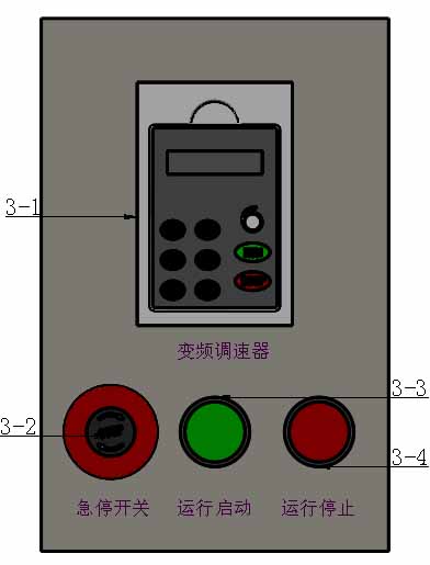
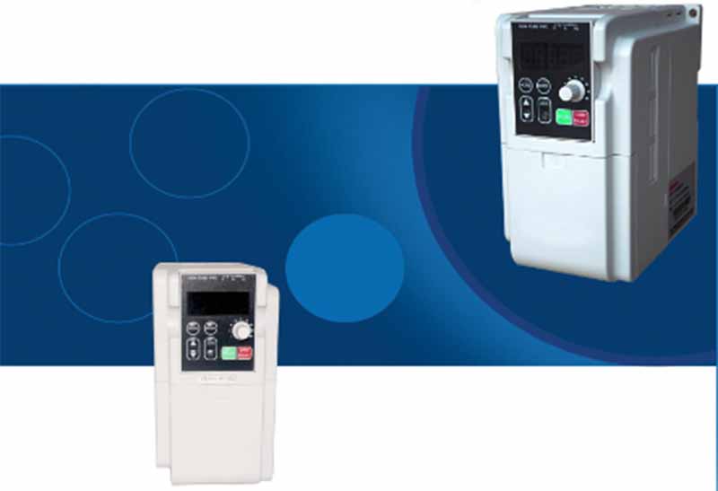
Figure 3: Schematic Diagram of the Soil Grinder Control Panel
3-1. Variable-frequency speed controller (displays the default speed on the screen);
3-2. Emergency stop switch;
3-3. Start button;
3-4. Stop button;
No-Load Test Operation Procedure:
① Connect the power supply and turn on the circuit breaker;
② Turn the speed control knob on the variable frequency drive (3-1) counterclockwise to the maximum position;
③ Activate the emergency stop switch (3-2) (the emergency stop switch is used to cut off power and stop the machine in an emergency;
④ when pressed, it is off; when rotated clockwise and in the spring-loaded position, it is on), and check if the VFD (3-1) displays a digital reading (if no display: check if the power connection is secure; if a display is present: proceed to the next step);
⑤ Press the start button (3-3) to start the equipment. Check whether the speed display on the variable frequency drive (3-1) returns to zero. Slowly turn the speed control knob on the variable frequency drive (3-1) clockwise to adjust the speed to half of the equipment’s rated maximum speed, and run it for 5 minutes.
⑥ If no abnormalities are detected, return the speed control knob on the variable frequency drive (3-1) to zero. Press the stop button (3-4) and the emergency stop switch (3-2) in sequence, then disconnect the power supply to shut down the equipment.
Note: Some models of the TR-04 series soil grinder are not equipped with a circuit breaker.
4.2 Ball Loading
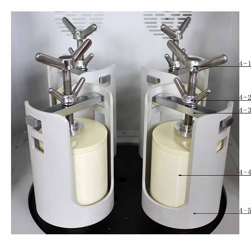
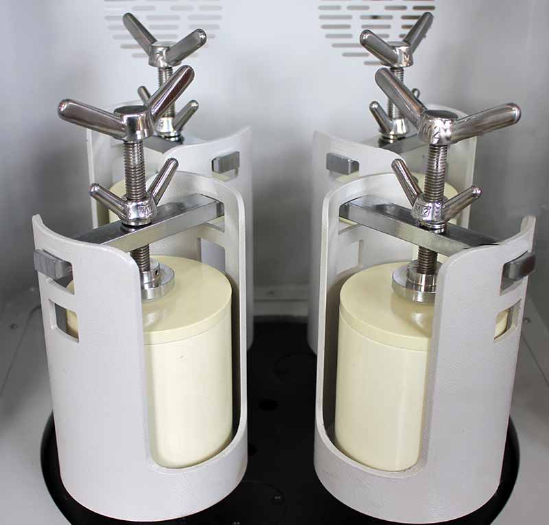
Figure 4: Actual view of the TR-04 grinding jar base and clamping device
4-1. Clamping rod; 4-2. Lock nut; 4-3. Crossbeam; 4-4. Grinding jar; 4-5. Grinding jar base;
To achieve optimal grinding results, a combination of large, medium, and small grinding balls is typically used. Large balls serve to provide a counterweight, crush the material, and disperse the smaller balls, while small balls are used for mixing and grinding the material. Under normal conditions, the total volume of balls and material should not exceed two-thirds of the total volume of the grinding jar (4-4).
Important Note: To prevent grinding balls and material from spilling into the equipment, which could cause wear on gears and bearings, first load the grinding balls and material into the ball mill tank (4-4). Then, install the filled ball mill tank (4-4) into the tank base (4-5). Do not install the empty tank first and then load the balls and material into it.
4.3 Loading the Mill Jar Loading procedure:
① First, place a rubber pad on the bottom of the mill jar base (4-5);
② Place the mill jar (4-4), loaded with grinding balls and material, into the mill jar base (4-5);
③ Insert the grinding jar clamping beam (4-3) into the corresponding position on the grinding jar base (4-5);
④ Tighten the clamping rod (4-1) to secure the grinding jar (4-4) within the grinding jar base (4-5);
⑤ Finally, tighten the lock nut (4-2) to secure the entire assembly.
Precautions:
① The ball mill vessels (4-4) must be installed symmetrically; operation with a single vessel or three vessels is prohibited. Ensure that the total weight of the two symmetrical ball mill vessels (vessel weight + ball weight + material weight) is as consistent as possible.
② The center of the ball mill tank (4-4) base should align as closely as possible with the center of the mill tank base (4-5);
③ When tightening the thrust rod (4-1) and the lock nut (4-2), ensure sufficient clamping force.
4.4 Power-On Standby
After connecting the equipment to the power supply, turn on the circuit breaker and activate the emergency stop switch (3-2) (rotate clockwise until it pops up). The variable frequency drive (3-1) will display a digital readout, and the equipment will enter the power-on standby state.
4.5 Setting the Variable Frequency Drive Parameters
(See the Planetary Ball Mill Variable Frequency Drive Operating Instructions for details)
4.6 Grinding
After setting the inverter function parameters, securely close the machine cover, press the start button (3-3) to start the equipment, and slowly turn the speed control knob (3-1) on the inverter to adjust to the set speed, then begin grinding.
Precautions:
① After the equipment has been running for 5 minutes, open the machine cover and check whether the grinding jar clamping device is loose. If it is loose, it must be retightened.
② The speed displayed on the variable frequency drive indicates both the motor’s rotational speed and the actual rotational speed of the ball mill tank;
③ A higher speed does not necessarily result in better grinding performance. Excessively high speeds will accelerate wear on the equipment’s mechanical components and shorten its service life. Users are advised to lower the grinding speed as much as possible based on the actual requirements of the material.
④ During operation, users must conduct frequent equipment inspections. If any abnormalities are detected, stop the machine immediately for inspection.
4.7 Shutdown
Once the equipment has been running for the set duration, turn the speed control knob on the variable frequency drive (3-1) to the zero position, press the stop button (3-4) and the emergency stop switch (3-2) in sequence, and disconnect the power supply to shut down the equipment.
Note: After turning the speed control knob on the variable frequency drive to zero, the equipment remains in a powered standby state. You must press the stop button (3-4) and the emergency stop switch (3-2), and then disconnect the power supply.
4.8 Removing the Grinding Jar
① Open the machine cover;
② Loosen the locknut (4-2);
③ Loosen the lifting rod (4-1);
④ Remove the clamping device;
⑤ Finally, remove the grinding jar (4-4);
4.9 Discharging
Pour the material and grinding balls from the ball mill tank into the ball-material separator (optional) to separate the balls from the material.
4.10 Equipment Cleaning
Clean the ball mill tank and grinding balls thoroughly and set them aside. Wipe the equipment clean inside and out with a clean cloth.
JXSC lab mineral processing equipment manufacturer has more than 38 years of experience in mining processing. We provide various lab mining equipment including gravity-separating equipment for processing minerals such as gold, tin, tungsten, lead, zinc, tantalum, niobium, iron, manganese, silver, titanium-iron, etc. Lab machines include laboratory jaw crusher, hammer crusher, roller crusher, grinding equipment, lab gravity separator, screening, washing equipment, etc. Welcome to consult!