These operating instructions are designed to help you quickly and safely configure the Frequency Inverter (U-Code) for ball mill applications. The parameter table provided in this document includes only the essential function codes that may be adjusted to suit your specific process needs. All other factory defaults are pre-optimized for reliable and efficient operation—please do not alter them without consulting us. Before starting, familiarize yourself with the button functions, display indicators, and the step-by-step setting procedure. Correct parameter setup ensures stable performance, extends equipment life, and prevents operational errors. If you encounter any code prefixed with “P” or “C,” stop and contact us for guidance.
Frequency Inverter Parameter Setting Guide
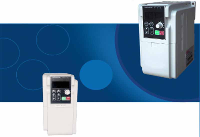
I. Button Functions
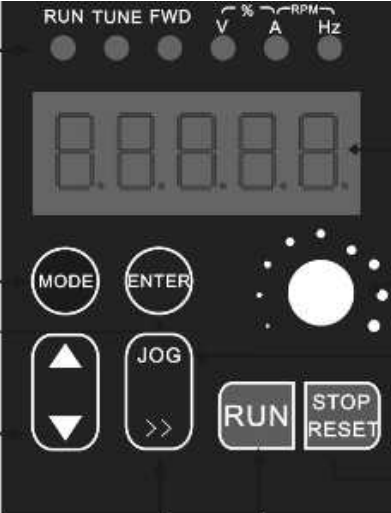
- ENTER Button: Scrolls through operating data in monitoring mode; reads and saves settings during parameter configuration. Press once , enter a setting option, and press again to save the setting.
- MODE Button: This button switches between programming and monitoring modes, and toggles between parameter display and the programming menu. When in the programming menu, pressing this button returns to the previous menu level.
- button: Function codes, menu groups, or incrementing parameter values.
- button: Decrease function codes, menu groups, or settings.
- button: Toggles between units of frequency, speed, voltage, current, etc.; moves the cursor when adjusting parameters.
- RUN button: In panel control mode, this button is used to start the inverter.
- STOP button: Press this button to stop the inverter; during a fault alarm, it serves as a reset button.
- JOG button: A jog button; press to start operation while in standby mode, and release to stop.
- Potentiometer: Adjusts the speed or frequency.
II. The table of inverter function codes
The table of inverter function codes is as follows (the factory default values for the function codes listed below may be modified as needed to meet specific requirements. Do not alter any other function codes or factory default values within the inverter; these parameters are specific to ball mills and are prefixed with “U.” If the prefix is ‘P’ or “C,” please contact our company; do not modify them arbitrarily).
Function Code | Name | Specified Range | Factory Default settings |
U3.0.02 | PLC Power-Off Memory Selection | Units digit: Power-off memory selection 0: No power-off memory 1:Power-off memory Tens digit: Shutdown memory selection 0: No shutdown memory 1: Shutdown memory 0
| 0 |
U3.0.04 | Stage 0 Run Time (Forward) | 0~6500 minutes | 10 |
U3.0.06 | Stage 1 Run Time (Reverse) | 0~6500 minutes | 10 |
U3.0.35 | Stage 0 Running Direction | H.010:Default Direction H.110:Reverse Direction | H.010 |
U3.0.36 | Stage 1 Running Direction | H.010:Default Direction H.110:Reverse Direction | H.010 |
U3.2.11 | Timed Operation Control (Timed or Not) | 4200:No Timer 4239:No Timer | 4239(Set to 4200 when using an external time relay) |
U3.2.17 | Interval Standby Time (Forward/Reverse Pause Time) | 0~3600 minutes | 0(Model) |
U3.2.24 | Total Run Time | 0~3600 minutes | 1000 |
III. Steps for Setting Frequency Inverter Parameters
3.1 The factory default values listed in the inverter function code table represent the parameter values set for that function code in the inverter system. To change these values, manually set new parameter values using the method described in Section 3.2.
Operating Instructions | Display |
1. Connect the power supply and turn on the switch | Displays the currently set speed value |
2. Press the MODE button once | Displays the function code, e.g., U0.0.11
|
3. Press the △ or ▽ button to select the function code you want to modify | Displays the current function code |
4. Press the ENTER key once to enter the parameter editing mode for the selected function code | Displays the selected function code parameter (factory default value) |
5. Press the 》 key to select the digit position you want to modify; the blinking digit indicates the value to be modified. Press the △ or ▽ keys to adjust to the desired value | Displays the function code’s factory default value and the modified value |
6. Press the ENTER key once to save the settings (to cancel, press the MODE key to return). | Proceeds to the next function code |
7. Repeat steps 3 through 6 to modify the parameter values of other function codes. | |
8. Press the MODE key once. | Displays the currently set speed value |
3.3 After powering on and entering standby mode, press the MODE button once. The display will show a code beginning with “U.” You can use the △ or ▽ buttons to change the currently displayed function code; the △ button increases the value, and the ▽ button decreases it. Once you have found the corresponding code, set the desired factory default value using the method described in section 3.2.
3.4 After all function code parameters have been set, press the MODE button once. The display will show the speed value and return to monitoring mode.
3.5 Function code U3.2.17: A pause time must be set between forward and reverse cycles for units 16L and larger.
Operating Mode 1:
- Unidirectional Operation (e.g., 5 minutes of operation, 1 minute of pause, total timed operation of 2 hours)
- Set the factory default value of Function U3.0.36 to H.010. Set the factory default values of Function Codes U3.0.04 and U3.0.06 (10 minutes) to 5 minutes for each operation; Function code U3.2.17: Change the factory default of 0 seconds to a standby time of 60 seconds after each operation; Function code U3.2.24: Change the factory default of 1000 minutes to 120 minutes.
Operation Mode 2:
- Forward and Reverse Operation (e.g., 5 minutes forward, 1 minute stop, then 5 minutes reverse, then 1 minute stop, total timed operation of 2 hours)
- Set the factory default value of function code U3.036 to H.110. Set the factory default value of function code U3.0.04 (10 minutes) to 5 minutes for each forward operation; set the factory default value of function code U3.0.06 (10) to 5 minutes for each reverse operation; Function code U3.2.17: Set the factory default value of 0 to a standby time of 60 minutes after each operation; Function code U3.2.24: Set the factory default value of 1000 minutes to 120 minutes.
Note:
- To reduce the risk of the processed material overheating and deteriorating, and to extend the service life of the main chassis components, the manufacturer recommends setting both forward and reverse rotation to 5 minutes each, with an interval of 30 seconds or longer.
- The factory settings for our equipment (i.e., the default inverter parameters) have been configured based on years of user feedback and are provided for reference only. If it is necessary to change the relevant parameter settings, please carefully read the “Inverter Operation and User Manual” before proceeding and be sure to modify the settings in accordance with the relevant steps, or contact our after-sales specialist for guidance. Under no circumstances should you arbitrarily alter the parameters. If improper settings or operation result in irreversible damage to the inverter, the user shall bear all costs associated with repair or replacement.
JXSC lab mineral processing equipment manufacturer has more than 38 years of experience in mining processing. We provide various lab mining equipment including gravity-separating equipment for processing minerals such as gold, tin, tungsten, lead, zinc, tantalum, niobium, iron, manganese, silver, titanium-iron, etc. Lab machines include laboratory jaw crusher, hammer crusher, roller crusher, grinding equipment, lab gravity separator, screening, washing equipment, etc. Welcome to consult!