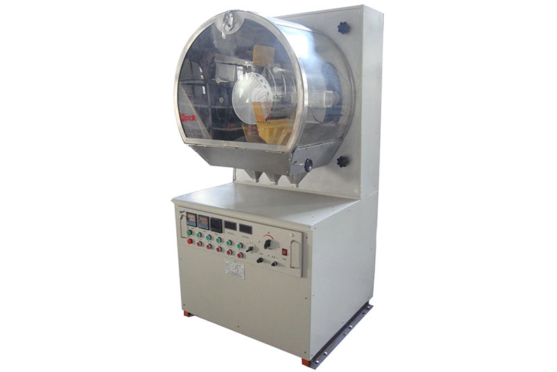
The XDF-φ250×200 High-Voltage Electrostatic Separator is primarily used for separating conductive minerals from non-conductive minerals. It can also replace screening operations for grading similar materials, as well as for grain processing and certain seed selection tasks.
Working Principle
When material is conveyed by the rotating drum into the high-voltage electric field created by the corona electrode and polarization, particles experience various forces, including Coulombic forces, non-electric field forces, interfacial attraction, centrifugal force, and gravity. Due to differing electrical properties among materials, these varying force states cause particles to follow distinct trajectories during descent, thereby achieving separation.
Details:
- Under the high-voltage electric field, conductive and non-conductive materials exhibit distinct force responses: – Conductive materials adsorb charges in the electric field but rapidly dissipate them. Under centrifugal and gravitational forces, they fall forward along the drum’s rotation direction.
- Non-conductive materials, possessing poor conductivity, cannot rapidly dissipate the charge absorbed from the high-voltage electric field. Consequently, an interfacial attraction force develops between these materials and the drum surface.
- This interfacial attraction overcomes centrifugal and gravitational forces, causing the material to adhere tightly to the drum surface until it reaches the rear. Materials with properties intermediate between conductive and non-conductive fall in the middle zone, referred to as neutral materials.
Technical Performance Parameters
No. | Item | Specification | Unit |
1 | Drum Diameter D × Length L | Ø250×200 | mm |
2 | Maximum Voltage | 60 | kV |
3 | Material Particle Size | 0.04~1 | mm |
4 | Processing Capacity | 15~30 | kg/h |
5 | Drum Rotation Speed n | 0~160( (Variable Frequency Adjustable)) | r/min |
6 | Hopper Heating Temperature T2 | 100~300 | ℃ |
7 | Drum Heating Temperature T1 | 50~80 | ℃ |
8 | Corona Electrode: Wire Diameter × Quantity | ø0.2×1~5 | mm×piece |
9 | Electrostatic Electrode: Wire Diameter × Quantity | ø30×1 | mm×piece |
10 | Electrode Adjustment: Distance Travel | 50 | mm |
11 | Angle Adjustment Range | ±15 | ° |
12 | Brush Dimensions: Outer Diameter × Core Roll Diameter | ø105×ø60 | mm |
13 | Brush Rotation Speed n0 | Twice the Drum Rotation Speed | |
14 | Hopper Gate Opening Scale | 0~20 | mm |
15 | Feed Angle Adjustment (Chute Inclination) | 0~20 | ° |
16 | Feed Rate Adjustment (Chute Vibrator) | 0~220 adjustable | V |
17 | Drive Power | 0.18 | kW |
18 | High-Voltage Power Supply | 800 | W |
19 | Human-Machine Interface (Touchscreen) | LC070SL | |
20 | PLC (Programmable Logic Controller) | LP-08M08R | |
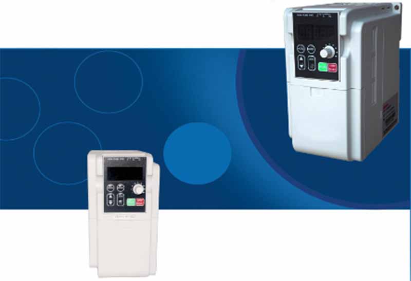
21 | Frequency Inverter | HLPC+00D423B | |
22 | Thermocouple | WRX-10,graduation mark:E | |
23 | Overall Dimensions: Length × Width × Height | 950×1150×1850 | mm |
24 | Weight | 390 | kg |
Overview of Mechanical Structure
To meet the specific demands of experimental research, numerous parameters during the sorting process must be adjustable and comparable. Designed specifically for experimental research requirements, this machine employs a “human-machine interface” (touchscreen) intelligent control mode, ensuring intuitive operation and a sleek, aesthetically pleasing appearance.
Structure details
- The transmission system employs a high-efficiency worm gear motor directly coupled to a reduction gearbox. Power is transmitted via V-belts to drive the coaxial distribution drum and brushes, ensuring differential rotation between them.
- The drum, brushes, and feeder are supported by cantilever structures, facilitating easy cleaning and maintenance of the entire assembly. An acrylic safety enclosure surrounds the experimental high-voltage electrostatic field work area formed by the drum, brushes, and feeder. An electromechanical interlock handle mechanism secures the enclosure door, ensuring safe and reliable operation.
- Adjustments to the feed angle, electrode angle, electrode distance, and mineral deflector plate angle are achieved through auxiliary movements of the worm gear mechanism, chain drive mechanism, and tension springs.
- The high-voltage power supply and electrical components are housed in the lower section. The work surface features an integrated stainless steel tabletop that maintains structural integrity.
- The material collection box is a 12cm diameter stainless steel container. It facilitates sample collection, division, and cleaning while preventing sample mixing and contamination. The electrical compartment includes a dedicated access door for power disconnection and maintenance.
- The base of the entire machine is fitted with four 75mm swivel casters, with the front two equipped with brake pedals for positioning. This design ensures both ergonomic suitability and the equipment’s functionality perfection.
Structural Diagram

- Feed chute angle adjustment knob
- Feed rate adjustment knob
- Hopper
- Feed vibrator
- Feed chute
- Door inter lock handle
- Drum
- Corona electrode
- Polarizing electrode (static electrode)
- Electrode Angle Adjustment Handwheel
- Front Divider Plate
- Front Divider Plate Adjustment Handwheel
- Electrode Distance Adjustment Handwheel
- Nameplate Panel
- High-Voltage Transformer
- Frame
- Casters
- Electrical access door
- Material collection bowl
- Drive motor
- Rear partition plate
- Rear partition plate adjustment knob
- USB port
- Micro printer
- Touchscreen
- Brush
Electrical Component List
The electrical components of the high-voltage electrostatic separator primarily include: high-voltage power supply, human-machine interface PLC control, electric heating, intelligent protection, variable frequency speed control circuits, etc. (see electrical schematic diagram).
XDF-250×200 High-Voltage Electrostatic Separator Electrical Component Specification List
No. | Code | Name | Model/Specification | Quantity | Remarks |
1 | Q1 | Main Automatic Switch | DZ47-63 D25 | 1 | AC220V 2pole |
2 | FU1 | Fuse | RT18-32 5A | 1 |
|
3 | FU2 | Fuse | RT18-32 15A | 1 |
|
4 | FU3、4 | Fuse | RT18-32 2A | 2 |
|
5 | KA1-4 | Intermediate Relay | HH52P | 4 | AC220 |
6 | SA1-3 | Proximity Switch | FA12-4KA,φ12 | 3 |
|
7 | TC | Thermocouple | WRX-10 | 2 | graduation mark: E |
8 | HE1、2 | Electric Heating Elements | φ20*150 300W | 6 | AC220V |
9 | TGTY1-3 | Power and Voltage Regulation Module | SAVP2215 | 3 |
|
10 | U1 | Single-phase AC voltage sensor | WBV414U01 250V | 1 | DC24V |
11 | U2 | Single-phase AC current sensor | WBI414S41 8A | 1 | DC24V |
12 | B1 | High-voltage voltage regulation module | MJYD-JL-75/380 | 1 |
|
13 | R | Resistor | RJ2W-150KΩ | 18 |
|
14 | M | Motor | YS-6314 0.18kW | 1 | 1400r/min |
15 | F | Inverter | HLP-C+00D423B | 1 | AC220V |
16 | PLC | Programmable Logic Controller | LP-08M08R | 1 | Mainframe |
17 | No. 1 | PLC Expansion Unit | ACS-2TC/2DA | 1 | Module |
18 | No. 2、3 | PLC Expansion Unit | ACS-2AD/2AD | 2 | Module |
19 | HA | Electric Bell | 3″ AC220V | 1 |
|
20 | B2 | High-Voltage Transformer | 60kV | 1 |
|
21 | KDY1 | Switching Power Supply | 5/12V DC2A | 1 | AC220V |
22 | KDY2 | Switching Power Supply | 24V DC2.5A | 1 | AC220V |
23 | P1 | Touch Screen | LC070SL | 1 |
|
24 | P2 | Printer | SP-EM40SK | 1 |
|
25 |
| USB Interface | 1.0 | 1 |
Operational Precautions
(1) Power Supply. Operating voltage: AC 220V. Power consumption: 3kW.
(2) This unit is high-voltage equipment requiring a dedicated ground wire with resistance below 4.
Operating Procedure
- Connect power supply: HMI (touchscreen) display activates.
- Press the “Power On” button. The power supply activates, the green indicator illuminates, and the main control power is engaged.
- Set the required heating temperatures for the drum and hopper: Set the heating temperatures for the drum and hopper, respectively. The digital display shows the target temperature values. When the measured object’s temperature falls below or exceeds the setpoint, the system automatically initiates the temperature control program to reach the set temperature.
- Press the “Drum Start” button. The drum starts, and the green indicator illuminates. Set the “Drum Speed Control”.
- Press the “Brush Close” button. The brushes close, and the green indicator light illuminates.
- Safety Precautions: To ensure personal and equipment safety, the front door is equipped with mechanical interlocks and electrical interlock devices.
(1)The door must be securely closed during operation. Turn the handwheel clockwise to engage the locking pin into the locking mechanism before initiating the high-voltage power supply. Press the “High Voltage” switch and lightly touch the “Auto Voltage Stabilization” button.
(2)The high voltage starts, the green indicator light illuminates, the voltage stabilization indicator flashes, and high voltage power is supplied. Observe the high voltage reading as the equipment automatically stabilizes to the required high voltage value.
(3)During operation, occasional “sparking” may occur for various reasons, causing high voltage overcurrent. To ensure a continuous operation, this machine incorporates an automatic protection circuit.
(4) If sparking is brief and infrequent, high voltage will continue functioning normally. Otherwise, the protection circuit will automatically disconnect the control circuit, halting equipment operation. Sorting may resume only after maintenance personnel complete repairs. - Press the “Feed Start” button. The feed start (green) indicator illuminates, and the feeder activates. Set the “Feed Adjustment” parameter to regulate the feed rate.
- Shutdown Procedure: Close the ore hopper gate, adjust high voltage to zero position. Sequentially press “High Voltage Stop,” “Brush Disengagement,” “Feeding Stop,” and “Drum Stop,” then set feed adjustment to zero. Press the “Power Stop” button to disconnect the main power supply.
- Cleaning the Sorting Chamber: Before opening the door, first remove the pin from the switch handwheel. Then turn the handwheel counterclockwise until the discharge rod contacts the electrode to initiate high-voltage discharge. Only then can the door be opened for interior cleaning.
JXSC lab mineral processing equipment manufacturer has more than 38 years of experience in mining processing. We provide various lab mining equipment including gravity-separating equipment for processing minerals such as gold, tin, tungsten, lead, zinc, tantalum, niobium, iron, manganese, silver, titanium-iron, etc. Lab machines include laboratory jaw crusher, hammer crusher, roller crusher, grinding equipment, lab gravity separator, screening, washing equipment, etc. Welcome to consult!